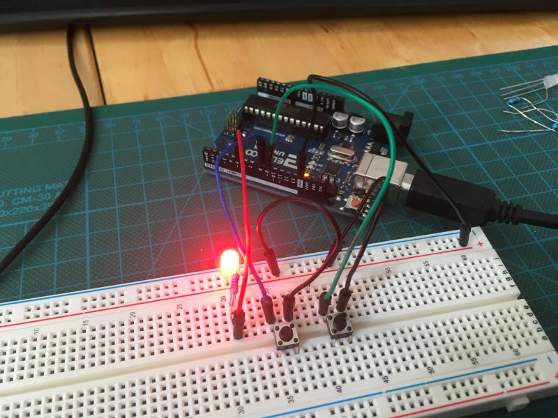
When I started my project to create a robot, I had only a vague idea of the required computer hardware. Reading about other robot projects, Arduino and Raspberry Pi are mentioned. Both are important computers, but for very different purposes.
In my microcontroller blog series, I want to investigate Arduino, Raspberry PI, their hardware functions and connection options. In this first article, I investigate briefly the differences between Arduino and Raspberry Pi and explain the concept of GPIOs.
This article originally appeared at my blog.
Microcontroller vs. Single-Board Computers
A microcontroller is a special type of computer with the primary focus of accessing and interacting with other hardware. It has only few resources in terms of CPU and RAM, but provides also very low power consumptions and the availability of real-time, fine grained processing of connected hardware. Also, a microcontroller does not have a full, general purpose operating system, but is very specialized for its use cases.
Single-board Computers, also called systems-on-a-chip, are small full-fledged computers. They provide current standard consumer-oriented interfaces like HDMI, USB, Wifi and Bluetooth. They offer SD-Cards or small SSD to store data, and have several CPU cores and RAM. SBC have a full operating system installed, typically a Linux or a Windows, and therefore provide a huge selection of general-purpose hardware.
An Arduino is a microcontroller, a board designed to interface external sensors and provides no operating system. A Raspberry Pi is a single-board-computer or system-on-a-chip and it runs a complete Linux operating system. Both systems are physically small and consume few amounts of energy, so they can be used for projects that are portable.
Both systems allow to interface with other Hardware through the uses of GPIO Pins, and they support different protocols and bus systems for connecting to other computers. For being concise, I will use the term microcontroller to refer to both the Arduino and the Raspberry Pi.
GPIO Pins
Microcontroller offer a limited number of digital signaling pins to the user. Pins can be broadly distinguished into digital and analog pins. Digital pins represent digital data, that is 0 or 1, as two different voltage bands, mostly 0V and 3.3/5.0V. Analog pins provide continuous values. They either provide a very fine grained voltage band, or use Pulse Width Modulation, a technique that "chops" a continuous signal into a frequency of different on/off voltages to represent data.
In a modern Microcontroller, only some pins serve a defined purpose, most importantly input/output of electricity and ground, or connection protocols. Most other pins are instead general purpose: Their concrete use is defined by the user.
As explained on Wikipedia, GPIO pins exists before popular microcontrollers or single board computers such as Arduino and Raspberry Pi were invented. However, GPIOs became popular with these boards because of their flexibility. To an Arduino, the user uploads a concrete program, called a sketch. The sketch can programmatically define the behavior of these pins: Do they serve as Input or Output? Are they providing digital or analog values? And even more, with the addition of Shields (Arduino)1 and HATS (Raspberry Pi, acronym for "hardware added on top"), special circuits are attached to the GPIOs to provide unique functionality, such as extend capabilities like Wifi and Bluetooth, or allowing precise control of actuators.
With this understanding, let’s take a look at the GPIO pins and the supported protocols for the Arduino Uno, the Raspberry Pi, and the Raspberry Pico.
Conclusion
This short article introduced microcontrollers, single-board computers and GPIO pins, the main interface with which to interact with other hardware. Starting with the next article, I will investigate the characteristics of the Arduino Uno, the Raspberry Pi and the Raspberry Pico.
Footnotes
-
Here is a good overview article about shields, and an extensive list of shields. ↩


